 Construction
The Megaprocessor is a fairly large contraption and took quite a long time to put together. It took a long time just to work out how to build it.
At the largest scale the Mega-processor consists of a series of "frames" 2m tall and of various widths from 1.2 to 1.6m. Within each frame is mounted a small number (2-4) of modules, the frame providing support and protection. Each module represents a collection of related functions within the processor such as the ALU, the decoder, etc. Each module shows a schematic/diagram of its part of the the logic of the system. On this schematic are mounted lots (few dozen) of small circuit boards, each board implementing a logic function. There are galleries with pictures of all the different elements :
Frames
These provide the main structural element, but there's more to them than just providing physical support.
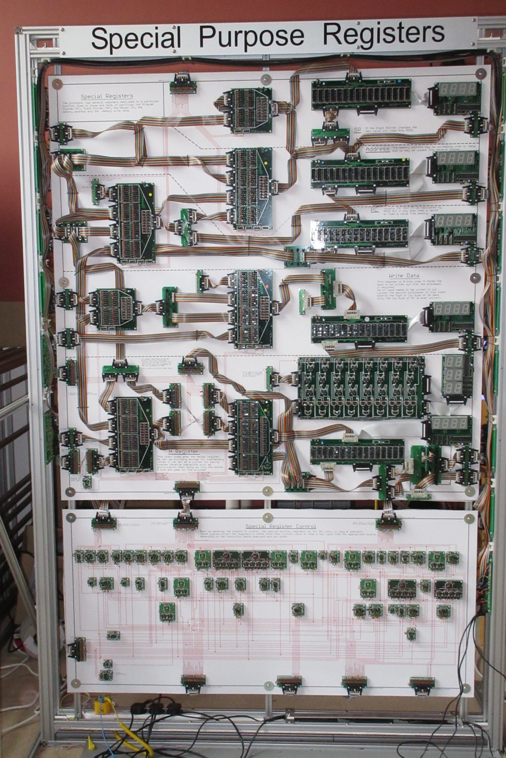
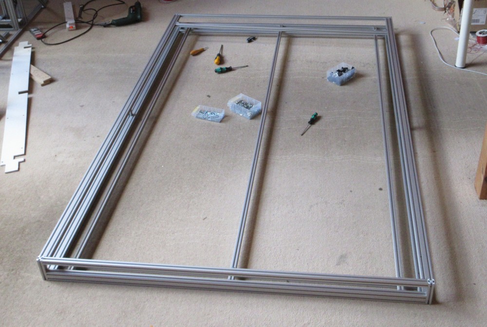
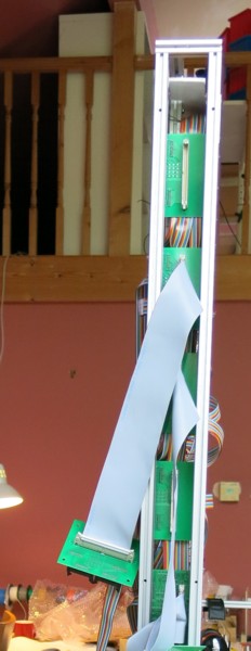
In essence a frame is just a shallow, 10 cm, box with some legs stuck on it. All made from extruded aluminium. For example the frame for the Special Registers:
It's easier to see the central core with this picture taken during construction.
A kind of channel is formed along the bottom to carry the power supplies:
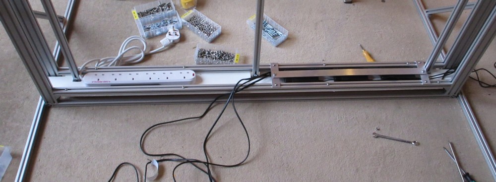
The bar over the power supplies is to keep them in place when moving the frame around.
In the picture above you can also the channel between the vertical supports. These provide mounting and protection for connections running between neighbouring frames.
All frames have a Services board mounted at the bottom on the right hand side verticals which you can just about see here:
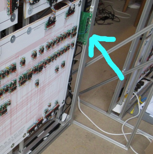
The services board has two functions. Firstly it provides connection to and monitoring of the power supplies. Secondly it provides access to the upstream and dowstream system buses. The downstream bus carries clock, reset, interrupts sourced from the control frame. The upstream, carries chip select (injected by the state machine frame) and write enable (injected by the Special Registers frame).
There are 7 frames, there is a gallery of them here.
Modules
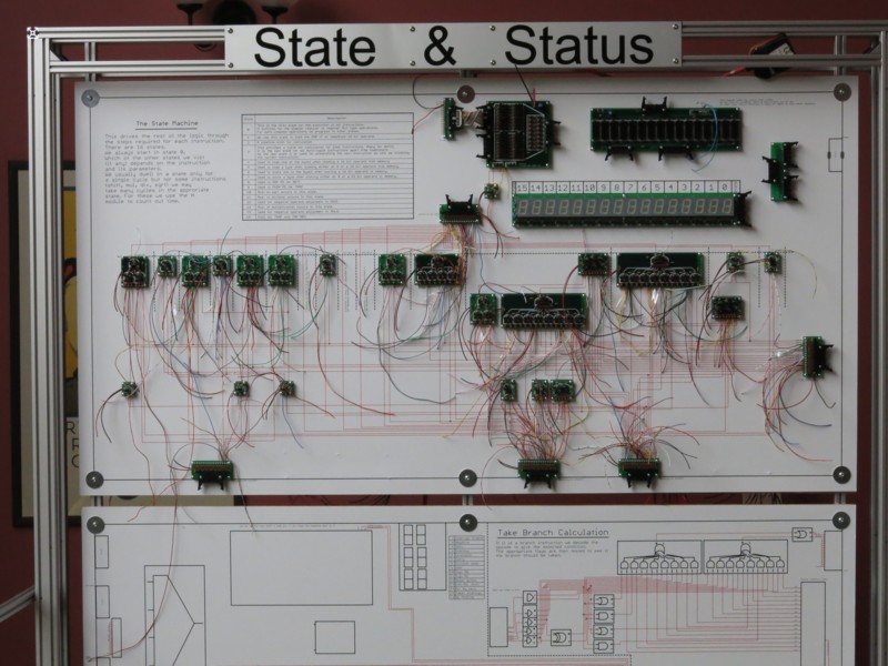
The Megaprocessor is split into a number of modules. For example here is the state machine module.
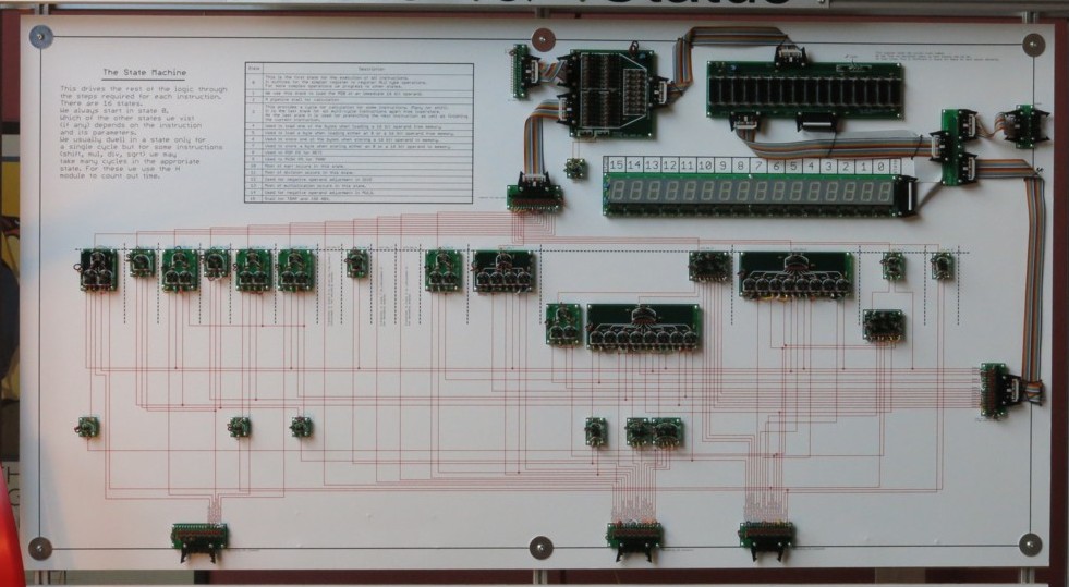
These carry the set of boards that implement the logic for that particular subsystem mounted on a schematic that shows how they are connected together.
The schematics are printed on card which is glued to plywood for strength and to give something that the boards can be screwed to.
Single point to point connections are made by wires behind the board. I did originally intend to have the wiring visible on the front but I couldn't think of a way of making it neat. As well as the single point to point control signals there are some 16 bit data buses which are made using ribbon cables.
From the point of having built all of the (tested) boards for a module it took about two weeks to construct a module. The first step is to drill holes for the point to point wiring and route the wires:
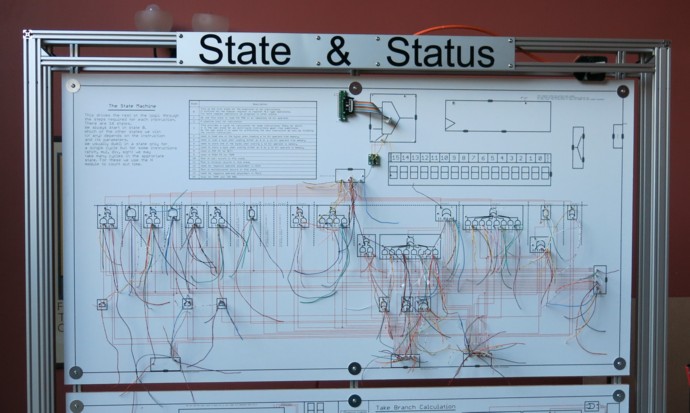
To help me do this I have a suitably reversed picture on the back of the module, so it looks like this:
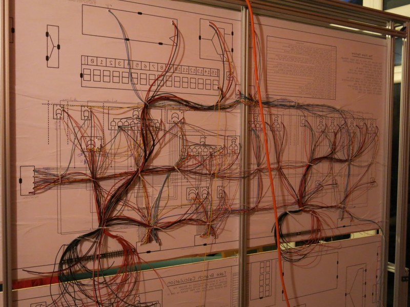
As I go along I mark up the wire colour I use both on the back of the module and also on a paper copy of the schematic so that I have something to refer to when working on the front side.
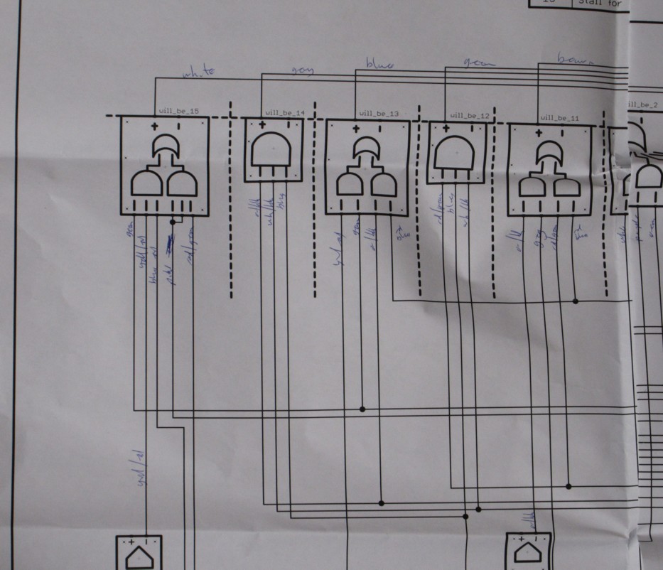
Noting the wiring colours not only helps for the building and debugging but also provides a sanity check for when I've finished. There should only be one colour on each connection and all connections should have a colour.
After I've done the wiring I then screw the boards on top:
Then the wires are clipped to size and soldered to terminals on the boards. Takes ages,
There is a gallery of modules here.
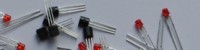
Boards
One of my earliest decisions when embarking on this project was that I would be making circuit boards. On this sort of scale point to point wiring of individual components (there'd be of the order of 100,000 connections) would result in inevitable failure, despair, insanity. Having these boards made represents the largest slice of the cost of the project. Initially I thought I would be doing a small number of very large boards. But that turned out to be bonkers so I've done a lot of little boards.
I use CadSoft's Eagle for schematic entry and PCB design.
All the boards have been manufactured by Tecbridge Circuits, http://www.tecbridgecircuits.co.uk/. (Very happy to recommend them.)
To make building the boards a bit easier I use the silkscreen to tell me what component value to use so I can build up the boards without having to refer to the circuit diagram. All the simpler functions generate both the positive and negative outputs so for example the AND can be used as either an AND or as a NAND etc. You can see both those aspects in the bare board below.
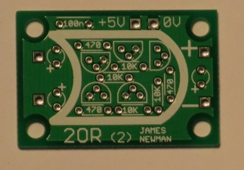
There is a gallery of the boards I've made here.
Test
Testing takes place at every stage of construction:
- Each board is tested by itself before mounting on a module
- Each module is tested on completion
- Each frame is tested on completion
- As each frame is joined to the next the ensemble is tested.
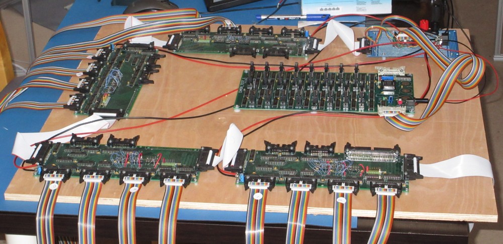
Testing is against the software model of the processor. There is a test program which incorporates the model of the processor. Depending on what is being tested the relevant part of the software model is used to generate a set of test patterns. In the test PC is an I/O card from BlueChip Technologies which allows the PC to talk to an I/O expander card I've built.
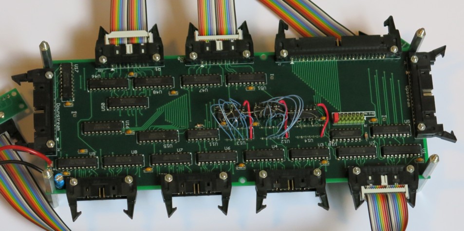
A single card gives me 32 inputs and 64 outputs in sets of 16 (my "standard" bus size). The boards can be daisy chained to give me the hundreds of I/O I need for testing modules and frames. Currently I have 4 and a bit (I tried to create an improved version. It didn't quite work so I've kept with the original, and added one of the semi-working new boards).
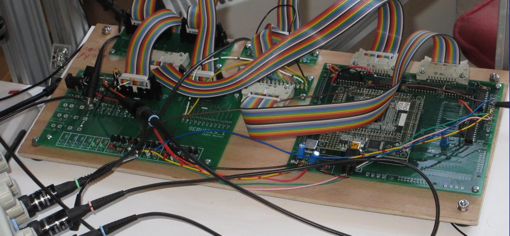
I also built a Megaprocessor emulator running out of the FPGA on an IGOR board. It took about half the FPGA. This was really useful for sorting out some of the interface issues.

© 2014-2016 James Newman.