 State Machine
There are 16 states. All instructions start executing in state 0. How many states the processor passes through to implement an instruction depends on the instruction. The states are:
| State | Action |
| 0 | This is the first state for all instructions, for the
simpler ALU instructions this suffices. For single cycle instructions the fetch of the next instruction will be occurring concurrently with the instruction operation in this state. For instructions requiring the load of immediate data the LSB will be loaded here |
| 1 | For instructions requiring the load of 16 bits of immediate data the MSB will be loaded in this state. |
| 2 | A stall cycle required for
some instructions for calculations to complete. The SHIFT instruction can use many cycles in this state. |
| 3 | This provides a cycle for calculation at the end of all
non load/store multi-cycle instruction. The fetch for the next instruction will occur during this state concurrently with the last calculation required for the instruction. |
| 4 | Used to load one of the bytes when doing a 16 byte load. |
| 5 | Used to load a byte when doing either an 8 or a 16 bit
load. Will be the last cycle of a load instruction. (The fetch for the next instruction will have been carried out during state 0 of the instruction with the result being held in the F register). |
| 6 | Used to load one of the bytes when doing a 16 byte load. |
| 7 | Used to store a byte when doing either an 8 or a 16 bit
store. Will be the last cycle of a store instruction. (The fetch for the next instruction will have been carried out during state 0 of the instruction with the result being held in the F register). |
| 8 | Used to POP PS during the RETI instruction |
| 9 | Used to PUSH PS during TRAP |
| 10 | Iteration for the SQRT instruction occurs during this
state. The H register is used to count the required number of cycles. |
| 11 | Iteration for the DIV instruction occurs during this
state. The H register is used to count the required number of cycles. |
| 12 | Used to carry out the adjustment required for negative operands at the end of a signed division |
| 13 | Iteration for the MUL instruction occurs during this
state. The H register is used to count the required number of cycles. |
| 14 | Used to carry out the adjustment required for negative operands at the end of a signed multiplication |
| 15 | A stall cycle used for JSR absolute and TRAP. |
The state is encoded using "one-hot" encoding and so uses a 16 bit register. The next state is calculated on the basis of the current state and signals generated by the decoding modules.
During RESET the state is coerced to 0 by a multiplexor.
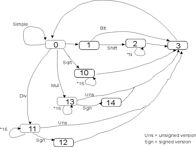
During iterative instructions (SHIFT, MUL, DIV, SQRT) the state machine may dwell in a state for more than one cycle. In these situations the H register is used to count out the required number of cycles.
All instructions start in state 0. Showing all possible state transitions on the one diagram leads to a quite crowded picture so I've split them into groups. First those used during arithmetic/logic operations:
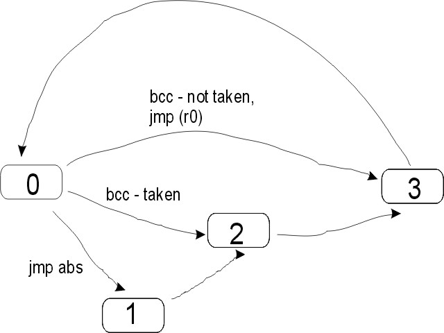
Branch and jump instructions follow these transitions
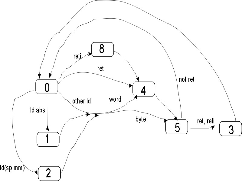
Read Instructions (load, ret, reti)
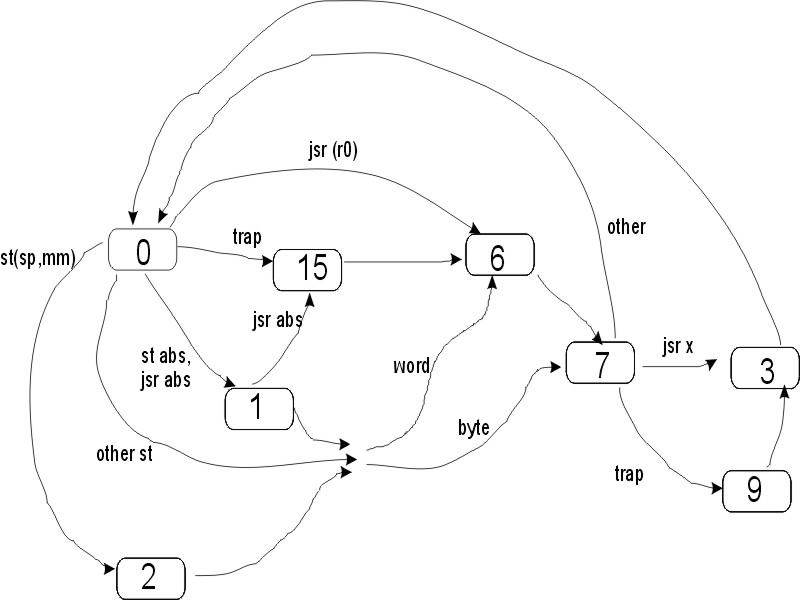
Write instructions (store, jsr, trap)

© 2014-2016 James Newman.