 DTL / TTL / CMOS NMOS
Several people have asked what kind of logic (as in DTL, TTL etc) I'm using, and why.
Until recently I generally replied "kind of TTL", afterall I was using transistors. When I first wrote this page I thought a bit more about it and changed my mind to answer "semi CMOS". A friend has since pointed out that actually this is NMOS logic and is described here on Wikipedia.
Most definitions of TTL talk of using multi-emitter transistors. I presume these are easy enough for the chip makers to build but I've never seen any as discretes.
The whole project started with the objective of learning about transistors so the answer was always going to be some kind of transistor logic but I did look around at other options once I'd decided I was going to build a processor. In my case DTL doesn't have any real attraction. It seems to use much the same number (if not more) of components as transistor based logic so size is much the same. Marginally cheaper but trivially so. A biggish downside in my view is that the fanout is quite low so you need to keep track of that and insert buffers as needed.
Looking at CMOS gates I found circuits such as that below for a NAND gate.
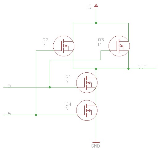
If you're approaching this circuit from the viewpoint of building some hundreds of them by hand the standout feature is that it implements the logic twice. You have one version yanking the output low when "0" and, a complementary version pulling the output high when "1". Makes sense for a chip maker but for me it's a definite no. So I chopped off the top half and replaced it with a resistor. Doing this we end up with NMOS logic. The C in CMOS stands for complementary i.e. it uses both P and N transistors. Using just N transistors makes it NMOS logic which was used a while back.
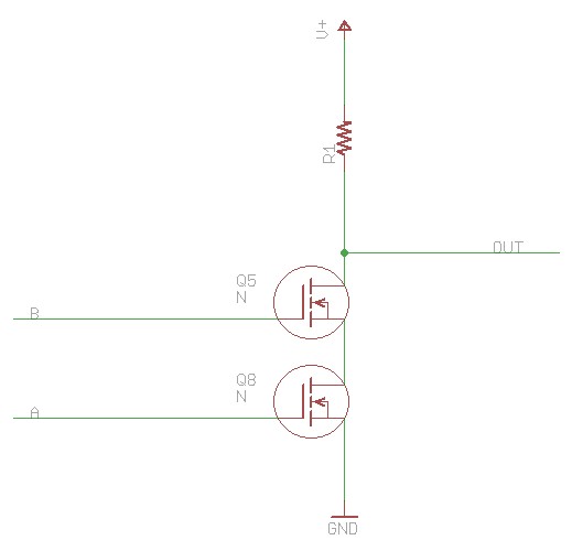
One consequence of this is that that it's much less power efficient. The proper circuit only draws significant current when switching (when both the top and bottom circuits might both be "on" concurrently as they transition state) whilst my version draws current all the time it is in the "0" state. However this is irrelevant in the case of the Megaprocessor because we're burning much much more power in the LEDs.
One of the benefits of using FETs is that the input impedance is extremely high so I get a huge fanout which means I can be relaxed on that front.
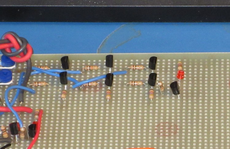
Actually my first thought was to use BJTs rather than FETs. As I mentioned at the start my initial motivation was to learn about transistors, and to my mind BJTs are more "proper" than are FETs. And here is a picture of the first logic gates I built (using 2N3904). First LEDs as well! I think the pair on the left was my first AND, and the next two pairs were my first XOR. It was a while ago.
I switched from the BJT (2N3904) to the FET (2N7000) when thinking about how this was going to scale. For this project resistors "cost" as much as transistors. They take as much space, and are more fiddly to insert in a board and solder. With a FET circuit you don't need the bias resistor that you need for a BJT based circuit. So you can roughly half the component count by switching to FETs. Also the fanout of the BJT logic gate is less.
- Home
- Vital Statistics
- Progress
- Architecture
- Stepping Stones
- Programming
- Peripherals
- Construction
- Cost & Materials
- Good, Bad & Ugly
- History
- Build Faults
- Flip Flops
- Modelling
- Architecture Choice
- Logic Type
- 7 segment
- Board Shape
- Dual Output
- ALU
- SRAM
- Speed
- Speed 2
- Buses
- Area
- Efficiency
- LED supply
- Multiplexor Problem
- Multiplexor Errors
- Surface Mount
- Solder
- Health & Safety
- Web
- Links
- Contact

© 2014-2016 James Newman.